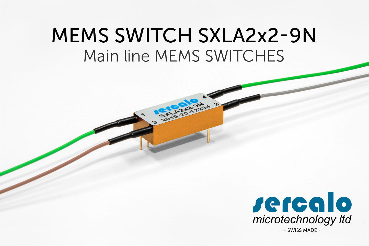
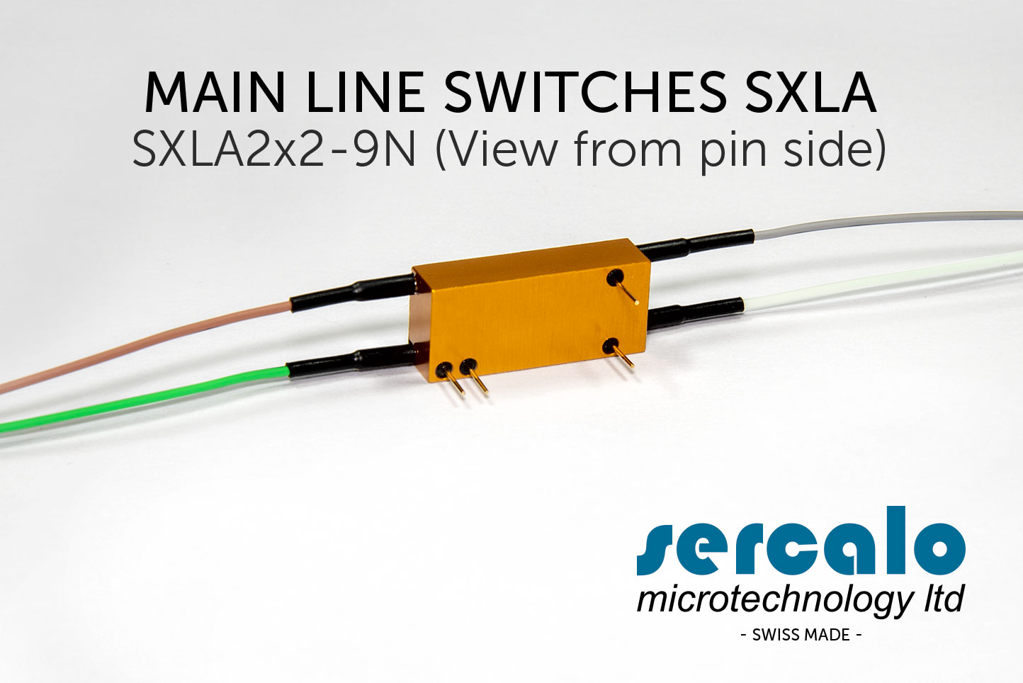
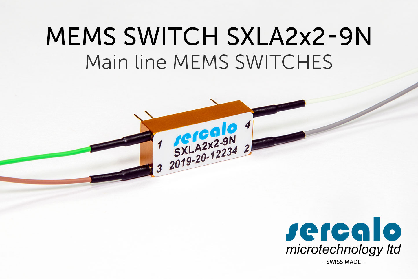
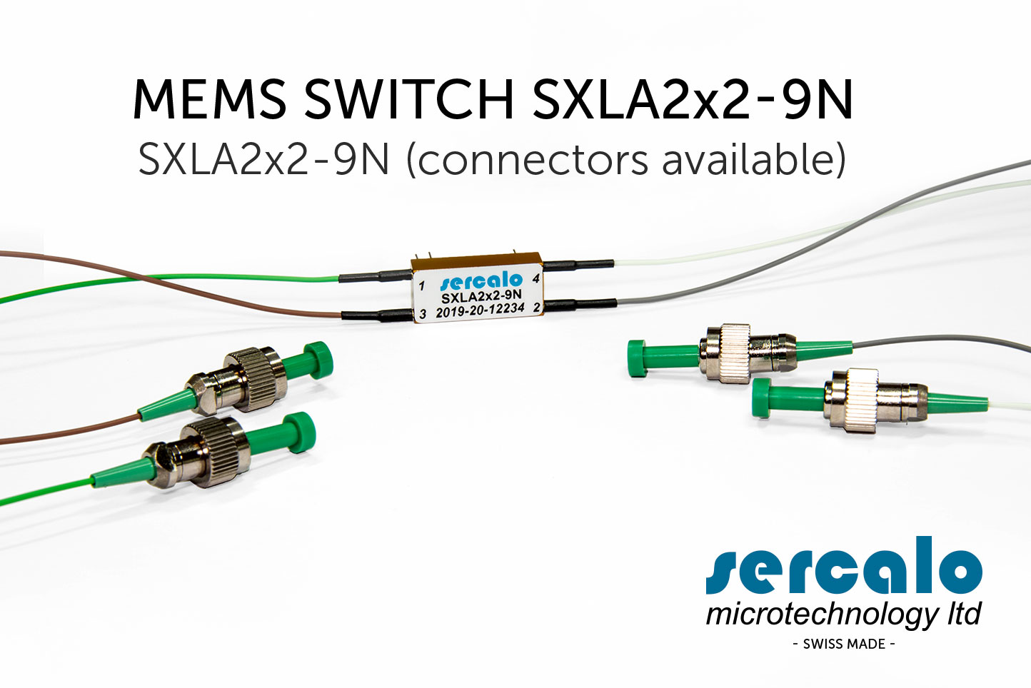
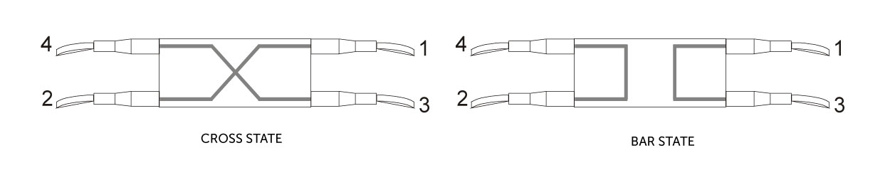
MEMS SWITCHES SXLA AND SXNA
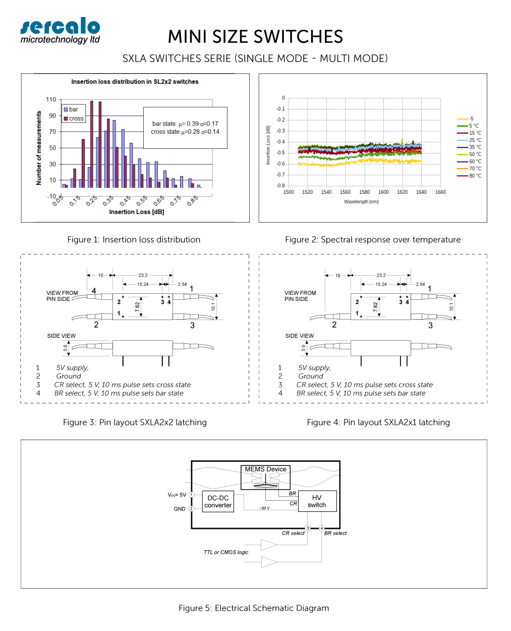
The SXLA are latching type switches for telecom and test and measurement applications. The SXLA achieve excellent repeatability and reliability. The single mode SXLA switch passes Telcordia GR1221 qualification.
The miniature SX switch is available as latching variant where a bistable suspension mechanism keeps the last selected state in power off. The non-latching type (i.e. SXNA) is not recommended for new designs.
# | FEATURES | APPLICATIONS |
---|---|---|
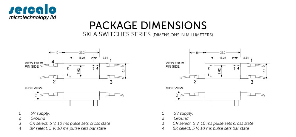
1 | 23 x 10 x 6 mm size | Protection Switching |
2 | Optimized for low cost production | Reconfiguration |
3 | TTL or CMOS logic | Optical Subsystems |
4 | Latching | Array integration |
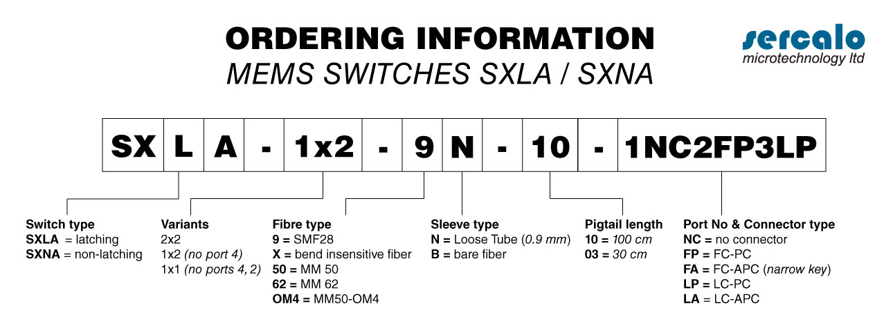
5 | 2x2, 2x1, 1x1 variants | Instrumentation Measurement |
6 | Single or multimode fiber | Medical |
BUY NOW
Information request Sercalo MEMS Switches
The SX Series are miniature opto-mechanical switches for fiber optic communication systems and submodules. The switch is available in latching variants, with 1x1, 2x1, 2x2. The switch offers smallest size, ease of integration and the established reliability of Sercalo’s MEMS components.
The package is one of the smallest in the industry. It is optimized for low cost production while maintaining high reliability. The component meets Telcordia GR1221 quality standards.
DESCRIPTION
In the SX Series the optical switching function is realised by a silicon MEMS chip, on which a mirror can be moved in and out of the optical path by electrostatic actuation. The miniature SX switch is available as latching variant where a bistable suspension mechanism keeps the last selected state in power off. The non-latching type (i.e. SXNA) is not recommended for new designs.
To operate the switch 5V and 0V are applied on pins 1 and 2, which are used by the internal DC-DC converter to supply a high voltage for the actuator control. CMOS or TTL logic levels on pins 3-4 control the electrostatic actuator. To set the switch state pin 3 respectively pin 4 are set to logic high (5V) for 20 ms and the corresponding switch state is selected. At rest pins 3 and 4 should be pulled to 0 V and must not be floating.
TECHNICAL SPECIFICATIONS
(for single mode fibers1)
Unit | Min | Typ | Max | |
---|---|---|---|---|
Switch | ||||
Wavelength range1 | nm | 1240 | 1640 | |
Insertion loss2 | dB | 0.4 | 1.0 | |
Crosstalk1 | dB | 75 | 60 | |
Return Loss1 | dB | 55 | 40 | |
Polarisation Dependent Loss | dB | 0.03 | 0.07 | |
Repeatability3 | dB | 0.002 | ||
Switching Time1 | ms | 2 | 10 | |
Durability | cycles | 10^9 | ||
Integrated Driver | ||||
Supply Voltage Vcc (pin 1) | V | 3.2 | 3.3 or 5 | 5.25 |
Current Consumption Icc (pin 1) | mA | 1 | 45 | |
Logic Level Low (pins 3, 4) | V | 0.3 | ||
Logic Level High (pins 3, 4) | V | 3.0 | ||
Selection Pulse Width | ms | 10 | 20 | |
Package | ||||
Operation Temperature | °C | 0 | 70 | |
Storage Temperature | °C | -40 | 85 | |
Size (L x W x H) – for single | mm | 23.2 x 10.1 x 6.0 |
1 for multimode: range: 600 – 1700 nm ; IL @ 1300 nm: 40 dB ; RL max: 35 dB ; resp. time: <20ms
2 value @ 25 °C, without connectors
3 for constant temperature and polarisation